🔗 Navigation
- Home
- The Challenge
- General System
- Software Subsystem
- Mechanical Subsystem
- Electrical Subsystem
- Thermal Subsystem
- End User Documentation & BOM
- Areas for Improvement
Electrical Subsystem
The electrical subsystem outlines the required components that are critical for the mission. This includes the flywheel sizing, power budget, flowchart, electrical circuit diagram and connections.
Flywheels
The launcher must propel a standard ping pong ball to a vertical height of at least 1.5 meters at the heat source.
Using the kinematics formula:
v² = u² + 2as
v² = 0² + 2 × (-9.81 × 1.5)
V = 5.4249 m/s
Using the linear-to-angular velocity relation:
N = (60 × Vf) / (π × d)
Where:
- d = flywheel diameter
- Vf = exit velocity
- N = RPM
| Flywheel Diameter (mm) | RPM |
|---|---|
| 30 | 3449 RPM |
| 35 | 2956 RPM |
| 40 | 2587 RPM |
| 45 | 2300 RPM |
| 50 | 2069 RPM |
| 57 | 1820 RPM |
Our flywheel size will be 57mm.
In normal operation, the likely throttle will be 10% since it is a large flywheel.
Assumed overall efficiency: 50%, to account for:
- Frictional losses
- Suboptimal contact with ping pong ball
- Interference fit inefficiencies
We are using two flywheels spinning in opposite directions.
Thus, each flywheel must run at: 1820 / 2 = 910 RPM
This gives us a total RPM of 910 × 2 = 1820 RPM
Motor Performance and Power Budget
- Motor rated max RPM: 24,975 RPM
- Motor current at max RPM = 6.5 A
- Expected throttle in real usage: 10%
- At 10% throttle:
(24,975 / 100) × 10 = 2497.5 RPM1820 RPM required → Sufficient for mission
- At 10% throttle:
- Motor current at 10% throttle:
6.5 / 10 = 0.65 A - Total current for 2 motors:
0.65 × 2 = 1.3 A - Power at 11.1V (3S LiPo):
1.3 A × 11.1 V = 14.43 W
Power Budget
| Components | Voltage(V) | Current(A) | Wattage(Maximum)(W) |
|---|---|---|---|
| Turtlebot max speed | 11.1 | 0.99 | 12.3 |
| Turtlebot idle | 11.1 | 0.81 | 9 |
| Feetech FS90R Micro Servo | 5 | 0.8 | 4 |
| AMG8866 x 2 | 3.3V | 0.0045 | 0.0297 |
| Motor of flywheel x2 | 11.1 | 1.68 | 14.43 |
| Speed controller x2 (90% eff) | 11.1 | 0.12 | 1.33 |
| TXS0108E Level Converter | 5 | ~0 | ~0 |
The logic converter is set to 0 as it draws 8×10^-6 A at worst.
Battery Life Estimation
Battery Specifications (TurtleBot3 Standard LiPo)
- Voltage: 11.1V
- Capacity: 1800mAh (1.8Ah)
- Energy: 11.1 V × 1.8 Ah = 19.98 Wh
- Average Power Usage (From Testing): 11W
Ideal Runtime (100% Efficiency)
Battery Life = 19.98 Wh / 11 W = 1.816 hours = 109 minutes
Adjusted Runtime (70% Real-World Efficiency)
109 × 0.7 = 76.3 minutes
Mission Duration Feasibility
- Single mission duration: 25 minutes
- Available runtime: ~76 minutes
- 76.3 / 25 = ~3 full missions possible
The TurtleBot3 battery provides enough power to complete the mission at least three times under real-world conditions, at 30% inefficiency.
Electrical Subsystem Connections
The electrical subsystem integrates sensor feedback, PWM motor control, and power distribution for the launcher mechanism and TurtleBot3 operations as shown here:
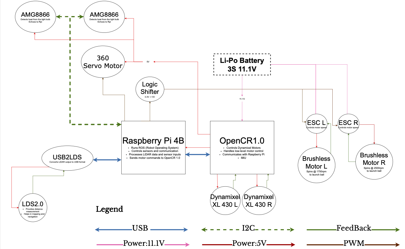
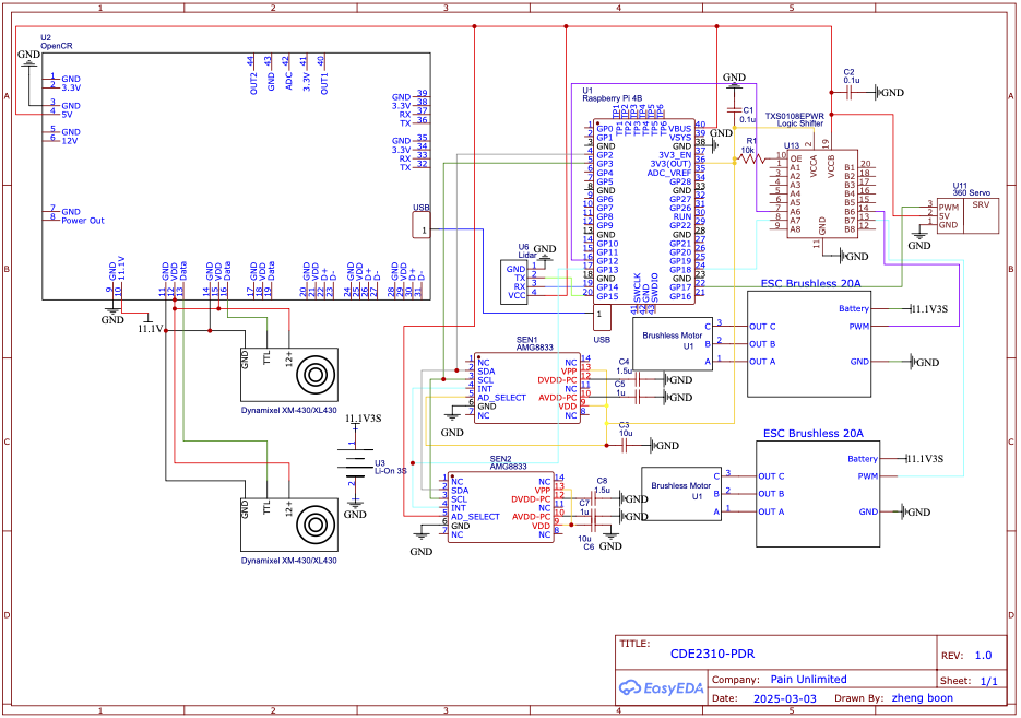
The circuit of the turtlebot is shown here
IR Sensor (AMG8833) Connection
- Sensor Type: AMG8833 IR thermal camera
- Interface: I2C
- Wiring:
- SDA (Data) → GPIO2 (BCM)
- SCL (Clock) → GPIO3 (BCM)
These sensors detect the heat signature of the target area and are connected directly to the Raspberry Pi I2C interface.
Flywheel Motor Control
- Motors: 2 × Brushless DC Motors
- Control Interface: ESC (Electronic Speed Controller)
- Signal Requirement: 50Hz PWM, with a 1ms–2ms pulse width:
- 1ms = minimum throttle
- 2ms = maximum throttle
- PWM Control Pins (BCM mode):
- Left Motor → GPIO18
- Right Motor → GPIO12
Raspberry Pi GPIO outputs are 3.3V logic, but ESCs require a 5V signal. A logic level shifter is used to step up the PWM signals to 5V.
Rack and Pinion Servo (Continuous Rotation)
Motor Type: 360° Continuous Servo
- Signal Requirement: 50Hz PWM:
- 1ms = full reverse
- 1.5ms = stationary
- 2ms = full forward
- PWM Control Pin:
- Servo Motor → GPIO17
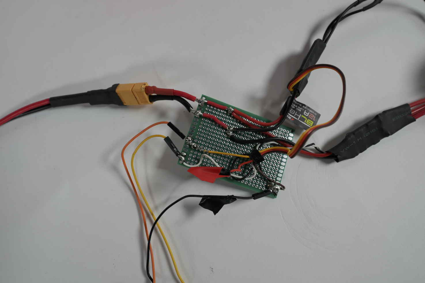
- Power Distribution
- ESC Power Input:
- Supplied via a split power connector (as shown in images) from the Raspberry Pi’s power input path.
- Shared 11.1V source from main LiPo battery.
- 5V & GND (Signal Side):
- Sourced directly from the Raspberry Pi 5V and GND rails.
- Common ground is ensured for consistent PWM signaling.
- Note: The OpenCR is powering the Raspberry Pi
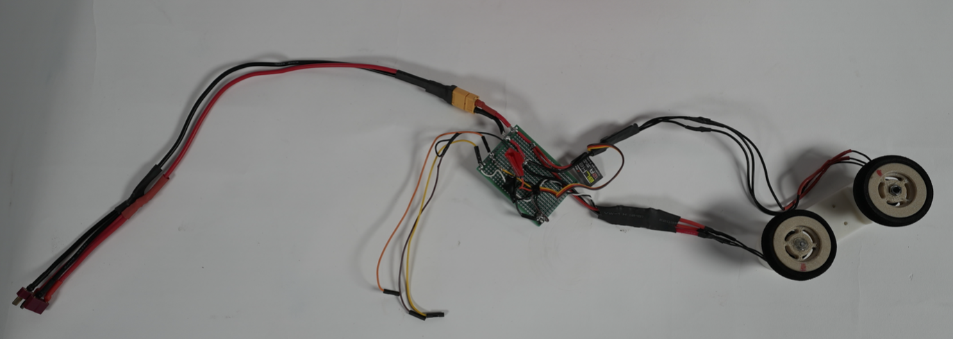
Connections
Shown in the pictures:
Battery split into TurtleBot and towards ESC.
The wire is split again into ESC L and ESC R.
The 3 jumper cables are for the ESCs and common ground.
Testing and Validation
Problems with Motor Calibration
- Significant differences in ESC calibration methods between manufacturers were discovered during the initial motor startup.
- Uneven motor speeds between the left and right flywheels were caused by certain ESCs that needed different throttle sequences to calibrate.
- A firmware mismatch was probably the cause of one ESC’s improperly calibrated starting throttle point.
- Due to a lack of compatible firmware flashing utilities, attempts to reflash the ESC using Arduino tools failed.
Unbalanced Flywheel Speed
- One flywheel continuously spun more slowly than the other, even though it was not difficult to reach a projectile height of 1.5 meters.
- The ball veered sideways due to this imbalance, occasionally striking walls before hitting the ceiling.
- To balance the velocities, a manual software offset was added to the flywheel PWM signal.
- Our issue was to keep the system from overshooting and hitting the ceiling, not to get enough power like other groups were trying to do.
Problems with Servo Upgrade and Positioning
- In order to actuate the rack and pinion for vertical ping pong ball movement, the original 180° servo lacked the necessary angular range.
- A 360° continuous rotation servo, which employs PWM for speed control rather than position control, replaced the previous system.
- Due to the lack of an absolute position reference, actuation timing had to be carefully adjusted using a helper function, which added complexity.
Jittering Servo Motor during ROS Startup
- GPIO noise during Raspberry Pi startup caused jitter in the servo motor when launching ROS2 (via
ros2 runorros2 launch). - The rack and pinion moved erratically as a result of this jitter.
- Software attempts to reduce the jitter were unsuccessful because the movement amplitude fluctuated erratically.
- Manually readjusting the servo position in between runs is a temporary fix.
- A limit switch at the tube’s base is suggested as a future solution to enable the servo to self-calibrate its depth, increasing repeatability and dependability.